Introduction
What is a VLAN? Is it some sort of highly expensive technology or virtual reality? Not at all. VLANs are relatively simple, yet they offer a wide variety of options and capabilities to improve your network.
VLAN, or Virtual LAN, is a technology that enables dividing
a physical network into logical segments at Layer 2. Functionally, VLANs enable a
network administrator to partition a network into separate, independent
networks. There are many reasons to separate a network into VLANs, and numerous options to consider.
While a useful technology for small LANS, VLANs are often deployed in large networks, too. In larger networks, VLANs are sometimes used to join physically separate LANs or LAN segments into a single logical LAN.
The goal of this article is to explain and discuss VLANs, including why you should consider using VLANs in a smaller network. I’ll also walk through a configuration example showing how to configure a VLAN-aware switch to create separate LAN segments.
VLANs and Switches
If you have more than one device on your network, you
probably have a switch. A switch is a simple device that operates at Layer 2 of
the OSI model, forwarding data frames from one device to another based on their
hardware or MAC (Media Access Control) address. The basic Layer 2 switch does not care or know about IP addresses, which operate at Layer 3.
Your switch may be a few ports built into your router, it may be a small unmanaged (non-configurable) switch such as the D-Link
DGS-2205 shown in Figure 1. Or you may have a more advanced switch with VLAN
capability, possibly referred to as a managed, "smart" or multilayer switch. Larger networks usually have multiple switches at numerous locations.
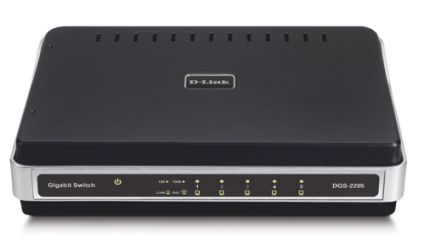
Figure 1: D-Link switch without VLAN capability
As stated, switches pass data from one device to another based on their MAC addresses. The key question is, how does the switch know which MAC address is located on which port?
Even the simplest switch has a “learning ability” to read
the MAC address of the devices connected, and store those MAC addresses in a
table in memory. Switches “learn” by examining the source MAC address of every
frame received. New MAC addresses learned on received frames are added to a
table, creating in the switch’s memory a mapping of MAC addresses to switch ports.
Broadcasts
VLANs become important when you consider broadcasts. Broadcasts
are frames sent to all devices on a switch, and in many cases, a normal and
frequent function. A broadcast domain is the set of all devices that receive a broadcast. Small LANs are typically equivalent to a single broadcast domain.
Devices on a network generate significant broadcast traffic.
Broadcasts normally occur when a device is trying to send data to another
device, but doesn’t know the MAC address of the destination device. A PC that knows the
destination IP, but not the MAC associated with that IP, will send a broadcast.
This type of broadcast is an ARP (Address Resolution Protocol) broadcast.
Devices, such as PCs, will build and maintain a listing of
IP addresses to MAC addresses in what is known as the ARP cache. The ARP cache
is temporary, can be overwritten, and is rebuilt every time the PC is powered on. In addition, entries expire after two minutes on Windows XP and 2000 PCs.
In a Windows PC, you can see the ARP cache by typing arp -a at the command line. In Figure 2, you can see the ARP cache of my PC, as learned from its network interface.

Figure 2: arp -a command showing ARP cache
Another example of broadcasts generated by PCs is DHCP
(Dynamic Host Configuration Protocol) requests. PCs will send DHCP broadcast
requests when they’re turned on to acquire an IP address, unless their IP has been statically configured.
Another source of broadcasts are switches themselves. When a frame enters a switch destined for a MAC address that the switch hasn’t learned—and that thus isn’t in the switch’s MAC table—the switch will broadcast that frame to all devices except the one that sent it, looking for a response.
The device with the desired MAC will respond to this
broadcast. The switch will then update its MAC table with what it learned from
the port on which the response frame was received. Like a PC, the MAC table of
a switch is usually stored in temporary memory, and will be rebuilt every time the switch is powered on.
IP multicasts are yet another source of broadcasts. Video can be sent over IP multicasts, which can consume tremendous amounts of bandwidth. For this reason, IP multicasting is frequently disabled in large networks and in most consumer routers by default.
Broadcasts can eat up considerable bandwidth on your LAN and they
also use processing power. Every device in the LAN receives broadcasts and must
read and determine whether or not to respond to each broadcast. As the number of devices in your LAN grows, so will the volume of broadcast traffic.
This is where VLANs become valuable—to break
up broadcast domains. Broadcasts are propagated within a VLAN, but not between
VLANs. By segmenting a network into VLANs, you will increase usable network
bandwidth, resources, and performance through the reduction of broadcast traffic.
Routers
Routers also break up broadcast domains. Routers operate at Layer 3, forwarding
packets based on IP addresses, not MAC addresses. A router will receive a frame
on its Ethernet interface, strip off the MAC address, and make a routing decision based on the originating and destination IP addresses.
Routing is an integral part of any network that contains multiple subnets and can play a key part in VLANs. VLANs can be configured on separate subnets, requiring a router to provide access to common services required by each VLAN.
For example, a network connected to the Internet usually employs a gateway router, which is probably also providing DHCP and NAT (Network Address Translation) services. If VLANs are created on different subnets, then the gateway, or another router will need to provide those services to each VLAN. In larger LANs, inter-subnet routing and VLAN segmentation is often handled by Layer 3 (sometimes called "multilayer") switches.
VLANs can also be configured to share a
single subnet, yet isolate various LAN members from each other. I’m going with the
single subnet approach here, using the SRW as my Layer 2 managed switch and a Linksys RV042 router (Figure 3) for Internet access, DHCP, and NAT.
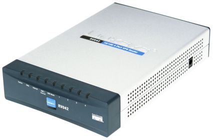
Figure 3: The Linksys RV042 router
How To
Now that you understand VLAN basics, let’s get to the fun part! I’ll be showing you how to segment a single-subnet LAN into multiple private segments.This basic application of VLANs is handy for adding an extra measure of security to clients or servers that contain confidential information. It can also be used in multi-tenant applications, to share a single Internet connection, yet allow each tenant to share files and printers without worrying about the others. I’m sure you can think of other applications.
I’ll be using a Linksys SRW2008 (Figure 4), an eight port 10/100/1000 switch with a nice web utility for configuration. The SRW (reviewed here) is a Layer 2 switch with a large number of features, including VLAN support.
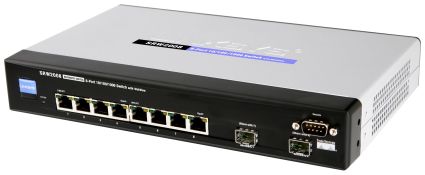
Figure 4: The Linksys SRW2008 switch
The basic steps in configuring a VLAN are:
- Plan your network.
- Create the VLANs.
- Associate switch ports with the VLANs.
- Test VLAN connectivity.
- Implement security measures as appropriate.
Planning
The most important part of VLAN
implementation, even in a small network, is planning. You need to review your
devices and decide which ones should go in which VLAN. A network administrator
must consider the components, functions, and traffic types of all the elements of the network when planning VLANs.
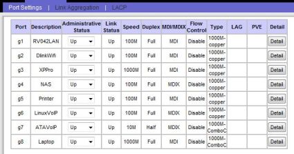
The network components connected to the eight port SRW switch
I’m using for this VLAN example are a LAN port from the RV042 router on port 1,
a WiFi router on port 2, a Windows Server on port 3, a NAS on port 4, a printer
on port 5, a Linux VoIP Server on port 6, a VoIP ATA on port 7, and a laptop computer on port 8. Figure 5 is a simple diagram of the “Before LAN.”
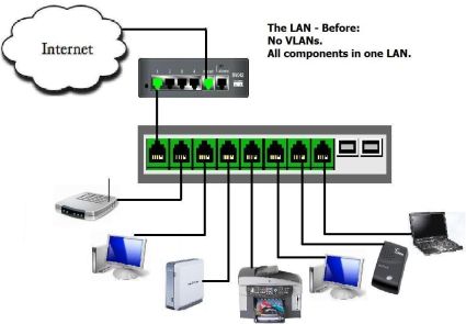
Figure 5: The network before dividing into VLANs
None of these components are “VLAN-aware,” meaning they will
send all frames to the switch “UnTagged.” VLAN-aware devices, such as VLAN-enabled switches, as well as advanced network interface cards, can specify VLAN
information by “Tagging” a frame with a VLAN number. This is an important factor when it comes to multi-switch configurations.
A common VLAN best practice is to place all VoIP devices in their own VLAN to prevents data traffic from interfering with time-sensitive voice traffic. So we have:
– a VLAN for the Data devices
– a VLAN for the VoIP devices
But I also need both Data and VoIP devices to have Internet access. So I’ll need:
– a VLAN to enable Internet access for both VLANs
This ability to allow ports to access multiple VLANs comes in very handy and is key to our example.
I’m also going to configure the Laptop switch port for access
to all VLANs and the management functions of the SRW. The SRW switch itself is also a member of the LAN, and has
its own IP address. It is important to remember this device and include it in a VLAN to retain access to the switch’s management utility. More on this later.
Mapping your network is a big part of the planning. The SRW
allows for naming the devices on each port, which is time well spent for the
future date when you’re troubleshooting. I took a few minutes and wrote down
which devices in my LAN were going to be plugged into which physical port on
the switch. I then configured the SRW with a recognizable name for each port in
the Description field of the Port Management menu (Figure 6), making it easier to see what was where.
Figure 6: Naming the ports
Create VLANs
With my planning complete, it’s time to
create the VLANs. Creating VLANs in the SRW is simply a matter of clicking
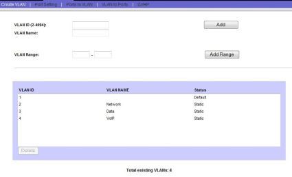
the “Create VLAN” menu and numbering and naming your VLANs. I’m splitting Voice
and Data on this network, yet I’m going to create three VLANs so I can name and fully manage all VLANs in use.
Figure 7 shows my created VLANs (2,3,4). Note that VLAN1 already existed in the SRW’s default configuration; this is the VLAN of the management interface of the SRW.
Figure 7: Created VLANs named appropriately
Map Ports
The next step is to map the physical switch ports to the
appropriate VLANs. This is a multistep process, and involves a couple of terms specific to the SRW. The
Linksys SRW has several port types for VLANs: Access, General, and Trunk. Other switches may use different terminology, so I’ll describe what these terms mean.
Linksys defines Access and Trunk ports similar to Cisco’s
definitions—which makes sense, as Linksys is a division of Cisco. An Access
port is one that belongs to a single VLAN. Frames received on ports configured
as Access cannot be modified, and more advanced VLAN port features such as filtering are disabled.
A Trunk port is defined by Linksys as belonging to multiple
VLANs in which all ports are “Tagged” with a VLAN ID. Two or more VLAN capable
switches can be configured with VLANs, connected together with trunks, and the
frames passed between them Tagged by the sending switch to identify the destination VLAN.
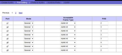
I’m using Linksys’ port type of General, which allows a port to be a member of multiple VLANs, and have the option of Tagging. I’m going to use the UnTagged option for all VLANs in this example.
Changing a port’s type on the SRW is done in the Port Setting menu (Figure 8), and there is a simple drop down selector for each port. I changed all eight ports to a Mode of General, and clicked Save.
Figure 8: Selecting the General port mode
Now that the VLANs are created, and we’ve configured the ports to allow membership to multiple VLANs, we can assign ports to VLANs. The end result (summarized in Table 1) I want is:
- Ports 1 and 8 to be members of the Network (2), Data (3), and VoIP (4)VLANs
- SRW management interface on the Network VLAN 2
- Ports 2–5 on the Network and Data VLAN 3
- Ports 6–7 on the Network and VoIP VLAN 4
| 1 | 2 | 3 | 4 | 5 | 6 | 7 | 8 | |
|---|---|---|---|---|---|---|---|---|
| VLAN 1 (Default) | ||||||||
| VLAN 2 (Network) | X | X | X | X | X | X | X | X |
| VLAN 3 (Data) | X | X | X | X | X | X | ||
| VLAN 4 (VoIP) | X | X | X | X |
Table 1: Port to VLAN mapping summary
The quickest way to do this on the SRW is via the Ports to VLAN menu. At the top, you select VLAN. You can’t edit any of the settings on
VLAN1, so I selected the VLAN indicated as “2, Network.” I want all ports to be
members of VLAN2, so I changed each port from the default “Excluded” button, to the “UnTagged” button, as in Figure 9.
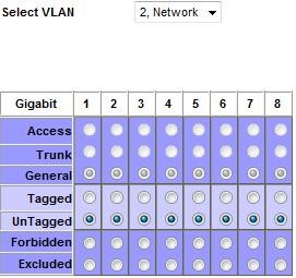
Figure 9: Configuring access to VLAN2
Next, I want ports 1–5 and 8 to be members of the Data VLAN, so I selected UnTagged for those ports for the VLAN indicated as “3, Data,” as in Figure 10.
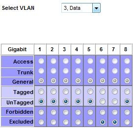
Figure 10: Configuring access to VLAN3
Last, I want ports 1 and 6–8 to be members of the VoIP VLAN, so I selected UnTagged for those ports for the VLAN indicated as “4, VoIP,” as in Figure 11.
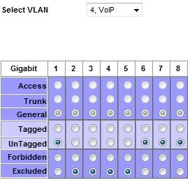
Figure 11: Configuring access to VLAN4
Set PVID
The next step is to change the PVID (Port Default
VLAN ID) setting on each port. The PVID is the VLAN ID the switch will assign
to all UnTagged frames received on each port. As mentioned, I’m not using
VLAN-aware devices, so all frames will arrive at the switch UnTagged. The frames will then receive the PVID associated with their port.
PVIDs are the key to breaking up a broadcast domain in this example! The simple rule to remember is that you set each port’s PVID equal to the number of the VLAN that you want it to logically belong to. This is where naming the VLANs is important.
So, my VoIP server and ATA are connected to switch ports 6 and 7, so I set both their PVIDs to 4, which I named the VoIP VLAN. Similarly, my data devices are plugged into switch ports 2 through 5, so they get a PVID of 3, which is the Data VLAN. Ports 1 and 8 are left over and get a PVID of 2, which is the Network VLAN.
Changing PVIDs on the SRW is accomplished via the Port Setting menu, and you simply put in the number of the VLAN that applies to all UnTagged frames arriving on that port, as in Figure 12.
Figure 12: Mapping PVIDs to ports
Click Save, and you’ve completed the configurations. I did
this on a live network; you would be wise to do this during little or no
activity on a production network. If you have a defined maintenance window, this type of work definitely belongs in that time frame.
One issue I ran into while configuring VLANs on this managed
switch was locking myself out of the switch’s management interface, which by
default is on VLAN1. The end result I’m going for will leave nothing on VLAN1,
so I’m going to have to change the switch’s default setting from VLAN1 while in VLAN1, and then go to a port in VLAN2 to complete the configurations.
The easiest way I found to do this is to change the PVID on
port 1, which is connected to the RV042, to a PVID of 2, and then change the network
setting of the SRW to VLAN2, as in Figure 13. I then moved the Ethernet cable
connected to my Laptop from port 8 of the SRW to a port on the RV042 to finish the configurations.
TIP: Some inexpensive managed / "smart" switches don’t have the ability to change the VLAN of the Management interface. In that case, you would use the default VLAN (usually either 0 or 1) as the "Network" VLAN in this example.
If you lock yourself out of the switch management interface, there is also a console connection option. On switches without console connections, you’d need to reset the switch to its default configuration and start over.
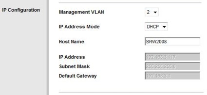
Figure 13: Putting the switch on a different VLAN
Testing
With the switch VLAN configurations complete,
it is time to test. The goal of this exercise was to separate the Data
components from the VoIP components, so pings from the Data to the VoIP VLAN and back are a good way to see if you’ve succeeded.
Indeed, pings from
components in the Data VLAN did not reach components in the VoIP VLAN, and vice
versa, which is what I want. However, all components need Internet access, so checking a browser on servers in both VLANs or pinging a reliable Internet host such as Google or Yahoo are good tests.
Since VoIP elements are part of this exercise, placing test
calls is a good idea, both to and from stations, as well as to and from outside
POTS numbers. Make sure to transmit and receive audio in both directions to
ensure no one-way audio problems. One-way audio would indicate a routing or firewall problem blocking the voice path of the communication stream.
Another benefit of VLANs is that my network is now more secure than it was as a single LAN. Any device can flood the network with
broadcast traffic, forming a denial of service attack against other devices on
the same VLAN. However, since broadcasts can’t cross VLANs, a device on my Data VLAN now can’t flood my VoIP VLAN.
With these steps completed, my network is now divided into
two separate VLANs and a third that overlaps the two. Figure 14 is a simple picture of my network with VLANs implemented. The four
devices on the left have access to each other and the Internet. The two VoIP
devices have access to each other and the Internet. Broadcasts in either VLAN will not affect the other.
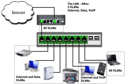
Figure 14: The network divided into VLANs
VLAN Best Practices
These are some general guidelines in creating VLANs. A VLAN creates a boundary between devices, so the goal is to plan the boundaries that will improve network functionality and security.
- Grouping devices by traffic patterns – Devices that
communicate extensively between each other are good candidates to be grouped into a common VLAN. - Grouping devices for security – It is often a good practice
to put servers and key infrastructure in their own VLAN, isolating them from the general broadcast traffic and enabling greater protection. - Grouping devices by traffic types – As discussed in this
How To, VoIP quality is improved by isolating VoIP devices to their own
VLAN. Other traffic types may also warrant their own VLAN. Traffic types
include network management traffic, IP multicast traffic such as video,
file and print services, email, Internet browsing, database access, shared network applications, and traffic generated by peer-to-peer applications. - Grouping devices geographically – In a network with limited
trunking, it may be beneficial to combine the devices in each location into their own VLAN.
More VLAN Technologies
In this How To, I’ve configured static VLANs. A static VLAN
is created by assigning switch ports to specific VLAN numbers. Some switches
may support dynamic VLANs, which are created by assigning MAC addresses to VLAN
numbers. Dynamic VLANs are a less common way to configure VLANs and are more
resource intensive to build and maintain. But they do enable mobility of devices while retaining VLAN boundaries.
As discussed, I didn’t use VLAN Trunking in this example. If I had multiple VLAN-aware switches, I would likely have employed Trunking to enable distributed VLAN configurations.
The standard protocol for VLAN Tagging is 802.1Q, sometimes referred to as Dot1Q. If you’re selecting a VLAN capable device, you’ll want to ensure this protocol is supported for interoperability, especially if you’re going to use it in VLAN trunking applications. The ability to change a port’s PVID usually comes along with 802.1Q capability.
Conclusion
The Linksys SRW2008 is a nice switch for
creating VLANs on your small network. Each of its eight ports support gigabit
Ethernet, so it could serve as a central switch connected to multiple other
switches. You could use less-expensive unmanaged switches to group devices,
and connect each unmanaged switch to a port on the SRW, using the SRW’s VLAN capability to break up the broadcast domains and maximize available bandwidth.
However, pretty much any managed or "smart" switch supports port-based VLANs, which is sufficient to implement the example in this article. Use the Gigabit Smart Switch Feature Comparison Table to explore other VLAN-capable products. Note, however, that the TrendNet TEG-160WS can’t be used because it doesn’t allow you to change port PVIDs.
A final plus to using VLANs is network design. VLANs enable
segmentation and grouping, which are recognized elements of good network design.
Good design makes network growth and maintenance easier. Being able to
eliminate all the devices in one VLAN as a possible cause of a problem in the other VLAN is a helpful and immediate benefit of having VLANs in your network.
With the right equipment and good planning, implementing a
VLAN is straightforward. Take your time and follow these steps, and you’ll be
rewarded with more bandwidth, increased security, and a better-designed network.

