Introduction
When I decided it was time to stop walking laptops around the house to test wireless products, I knew we had to move to anechoic RF chambers to automate the process. But simply throwing a test laptop in one box and the router under test into another and connecting them via programmable attenuators wasn’t enough.
The problem is that today’s MIMO-based Wi-Fi products—802.11n and the upcoming 11ac—rely on bouncing their signals off various surfaces during their travels. These reflections slightly delay the arrival of signals from the multiple radios and create the multipath that is essential for MIMO to work.
With signals traveling inside reflectionless (anechoic) R.F. sealed boxes and via shielded cables, there would be no reflections and no multipath. So measurements taken with such a setup would be far removed from real-life performance.
Fortunately, I knew who to take the problem to. octoScope was launched a few years ago by Fanny Mlinarsky, who was also a founder of Azimuth Systems. I also know Fanny from my previous life in the automatic test industry.
Long time readers may remember Azimuth loaned us its channel emulator and RF enclosures for a relatively brief experiment with closed-chamber testing back in 2007.
Fanny had approached me a few years back when octoScope launched its original octoBox anechoic RF test station. So when I started to think about closed chamber testing, I knew where to turn. Since our original discussion, octoScope had introduced its smaller octoBox Stackable enclosures, which were both the right size and right price for what I needed.
As we talked about the testing requirements, it became clear that some sort of multipath generator was needed, but it had to be much less expensive than the digitally-based MIMO channel emulators available from Azimuth and others.
After some brainstorming, octoScope proposed an analog multipath emulator that looked like it would meet our needs. The patents pending octoBox MultiPath Emulator (MPE) generates reflections using cable stubs that create multipath closely approaching the IEEE 802.11n/ac Model B, which is intended to emulate home and small office environments. The octoBox-MPE can be configured to support up to 4×4 MIMO. This octoScope whitepaper has more technical details about the MPE’s design.
We tested a prototype of the MPE last November and took delivery of the first production model and two octoBox Stackable enclosures at the end of March. Here a shot of what the whole shebang looks like.

New SmallNetBuilder Wireless Testbed
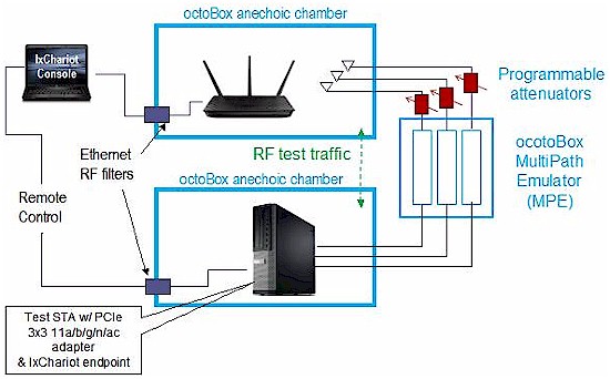
The new SNB Wi-Fi testbed uses two dedicated computers running Windows 7, with everything connected as shown in the diagram below. As in our previous wireless test methods, the new process also uses Ixia’s IxChariot to generate and measure wireless throughput. The latest version of IxChariot also allows us to measure RSSI during uplink tests.

octoBox based WLAN Testbed block diagram
In the testbed, one computer is a Win 7 laptop (Intel U7300 @ 1.3 GHz) that runs the IxChariot console and one of the test endpoints. This is connected to the router or access point under test that sits in the upper cabinet. The signals from the router under test are picked up by three omnidirectional unity-gain 2.4 / 5 GHz dual-band antennas, shown in the photo below.

Router under test inside the upper test chamber
The three antennas are connected to three Vaunix LDA-602 Lab Brick programmable attenuators that are used to adjust signal level to simulate distance. The attenuators can be seen in the first photo above, mounted on the side of the upper test chamber. The outputs of these attenuators are connected to a set of connectors on the octoBox MPE, which sits between the upper and lower stackable octoBox chambers. The other set of connectors on the MPE connect directly to the lower test chamber, which holds the standard wireless test client (STA).

Standard test client in the lower test chamber
The test client shown in the photo above is another Win 7 computer (Core i5-2400 @ 3.1 GHz) that runs another IxChariot endpoint and is home for an ASUS PCE-66U AC1750 PCIe adapter shown below. The adapter is directly cabled to the MPE. This was necessary to ensure high enough signal levels in both 2.4 and 5 GHz so that maximum link rates could be reached.
The RF path loss is actually low enough in the 2.4 GHz band so that we could have used antenna coupling in both chambers. But higher path loss in the 5 GHz band meant we needed to take the antennas out of the path in the STA test chamber.

ASUS PCE-AC66 Dual-Band Wireless-AC1750 Adapter
The ASUS adapter was chosen because it is the only adapter available that supports the maximum 1300 Mbps link rate for 3X3 draft 802.11ac and all the 802.11a and n link rates. It also supports 2.4 GHz 802.11b/g/n link rates up to 450 Mbps. Given that we will be living with this adapter for the next few years or so as our new test standard, we reached out to both Broadcom and Qualcomm Atheros to see if there were any alternatives before we chose the ASUS and found none.
The new testbed will allow us to perform more testing in less time than the old method. It will also enable more detailed performance analysis such as shown in the composite plot below.

Example data from the new testbed
The specifics of the new wireless test procedures are in development and will be finished soon. When the procedures are completed, we’ll be able to test more wireless products than ever before to ensure that SmallNetBuilder remains your best resource for wireless router research and selection.
